Case Studies
Analysis that held up in review.
Selected project work, followed by the verification benchmarks we use to prove out our methods. Client names are withheld unless we have permission to share them.
Structural FEA · Automotive fluid systems
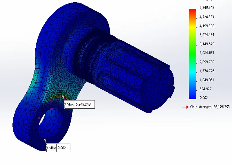
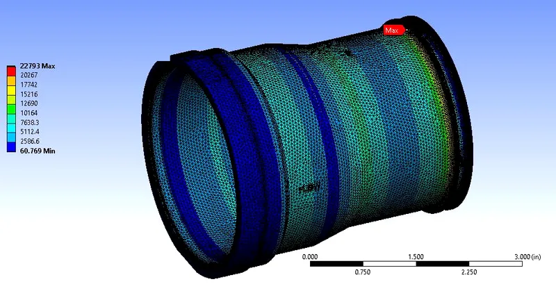
Pressure qualification of a glass-filled polymer housing
Challenge. A customer needed confidence that a 40% glass-filled PPS housing would survive working, proof and burst pressure, including at 300 °F where the plastic loses most of its strength.
Approach. Three load cases were run: 120 psi working, 150 psi proof and 180 psi burst. Supplier temperature data was used to derate tensile strength from 190 MPa at room temperature to 65 MPa at 300 °F. The mesh was refined at stress concentrations until results changed by less than 3% between runs.
Result. Peak stresses of 5,249, 6,561 and 7,873 psi gave a positive factor of safety in every case, including burst pressure at temperature. That supported moving to qualification testing with the proposed material and a high-temperature alternative.
Electromagnetic Simulation · Aerospace sensors
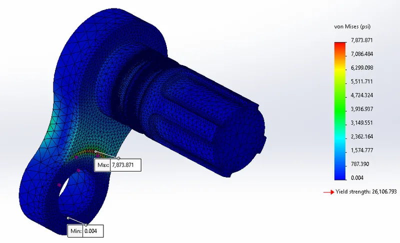
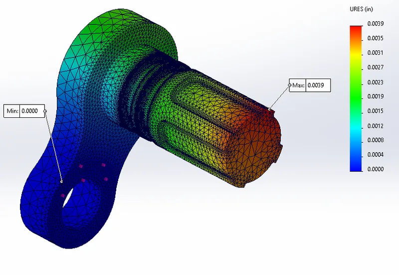
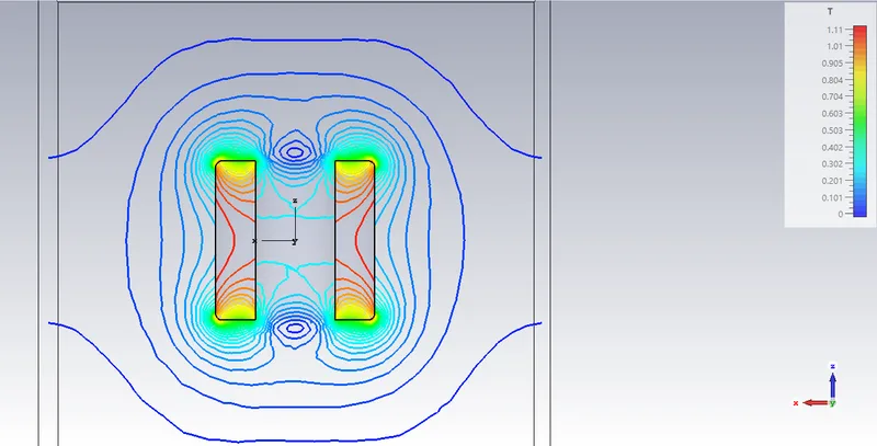
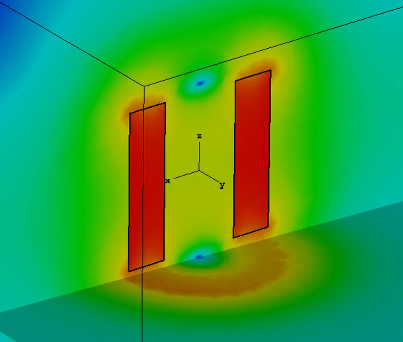
Magnet geometry study for a debris sensor
Challenge. A magnetic sensor's sensitivity depends on the shape of the field near the magnet. Small geometry changes such as a countersink, chamfer or counterbore can move or weaken the region the sensor relies on.
Approach. An N42 neodymium ring magnet and six geometry variants were modeled in electromagnetic simulation. Flux density was extracted along the centerline and across the cross-section of each.
Result. A side-by-side comparison of field strength and null-point location for each variant, which narrowed the design to the geometry best suited to the sensor before any magnets were ordered.
Structural FEA · Aerospace fuel systems
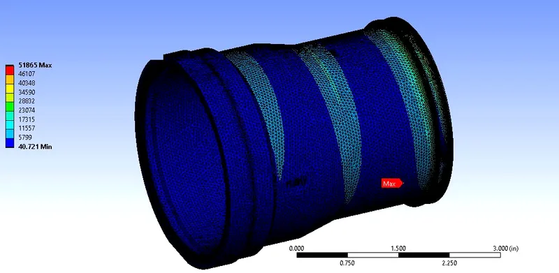
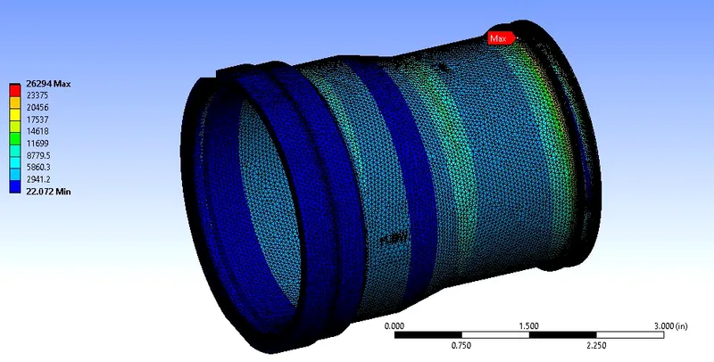
Pressure-surge loading of a fuel-system valve body
Challenge. An updated system requirement added pressure-surge (water hammer) loading to an existing aluminum valve body. The question was whether the qualified design could absorb the new loads without a redesign.
Approach. The surge requirement was converted into three static load cases, each combining internal pressure with axial load, shear and bending moment at the interface. Each case was solved in Ansys Mechanical and compared with the alloy's yield strength and its fatigue endurance limit at operating temperature.
Result. Combined stresses exceeded the endurance limit in every case, and the worst case reached roughly two and a half times that limit. Based on that margin, we recommended a material and design change rather than qualification by similarity, before any hardware was committed to test.
More Project Work
Aerospace, defense and industrial analysis
Vibration Analysis · Turbofan engines
Engine oil level sensor vibration
Modal and random vibration analysis of an oil level sensor mounted on commercial and military turbofan engines, used to confirm resonance margins and fatigue life against the engine vibration environment.
CFD · Defense
Pressure drop through a fluid-system component
CFD of internal flow to predict pressure drop and flow distribution across the operating range, which drives pump sizing and system-level performance.
Structural FEA · Military aerospace
Fifth-generation fighter aircraft component
Structural analysis of a flight-hardware component for a fifth-generation fighter program, covering pressure, vibration and thermal loading against program requirements.
Structural FEA · Industrial equipment
Heavy-duty equipment cart
Frame and weldment analysis of a mobile cart under rated load, including caster and handle loads, to confirm stress and deflection margins.
Structural FEA · Fluid systems
PAO hydraulic fluid skid
Structural analysis of a skid-mounted PAO hydraulic fluid system, covering lifting, transport and operating loads on the base frame and component mounts.
Verification Benchmarks
Methods you can check
Time-marched CFD runs and problems with known textbook answers. The textbook images are generated from those reference solutions, and our models are checked against them.
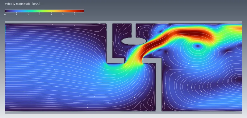
Globe valve flow (time-marched CFD)
Velocity and streamlines: the seat jet reaches about 6× inlet velocity, with recirculation on both sides.
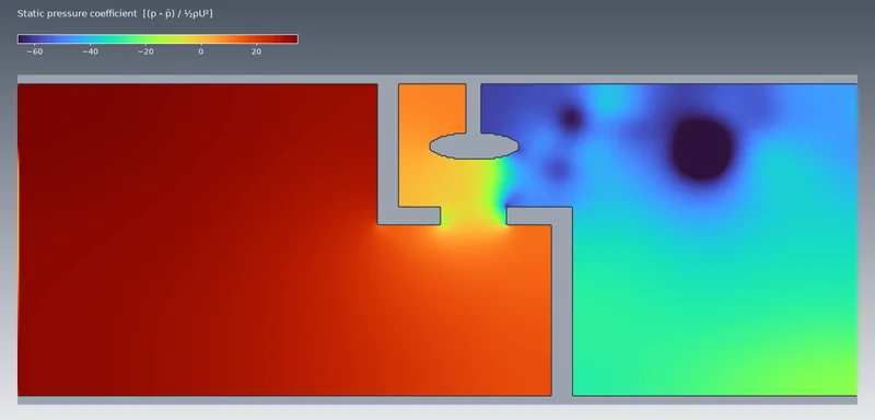
Globe valve pressure drop
Static pressure falls sharply across the seat and plug. This is the loss that sets pump and valve sizing.
Vortex shedding (time-marched CFD)
Alternating vortices at Re = 150. The shedding frequency sets flow-induced vibration of pins, probes and tubes.
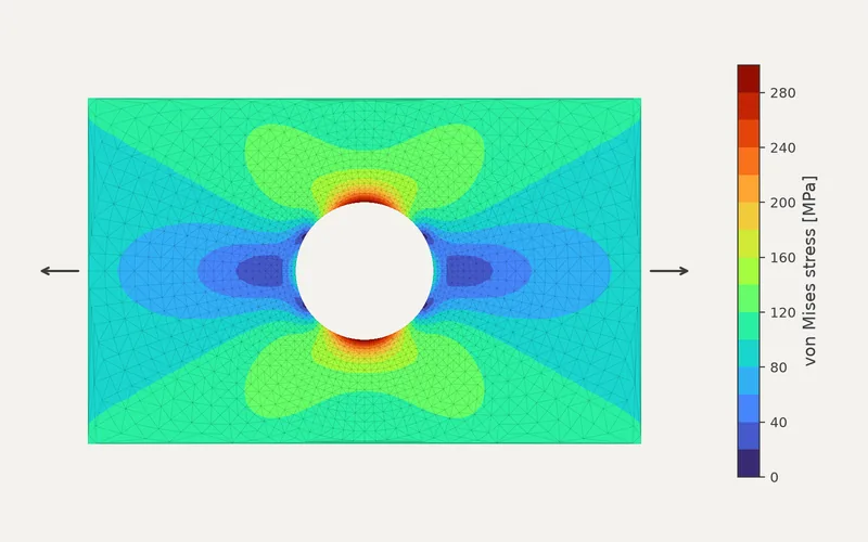
Stress concentration at a hole
Peak stress reaches three times the applied stress (Kt = 3.0), matching the Kirsch solution.
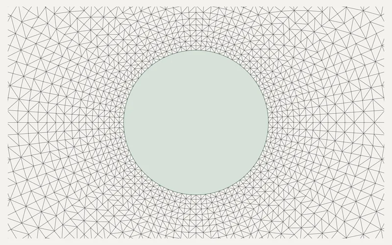
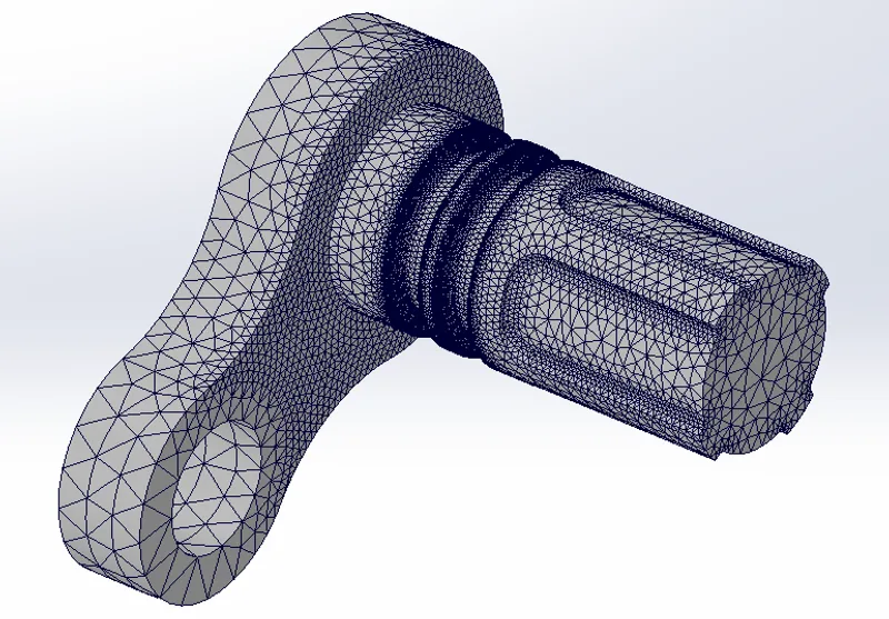
Mesh refinement
Element size graded from the stress gradient outward, and re-solved until the answer stops changing.
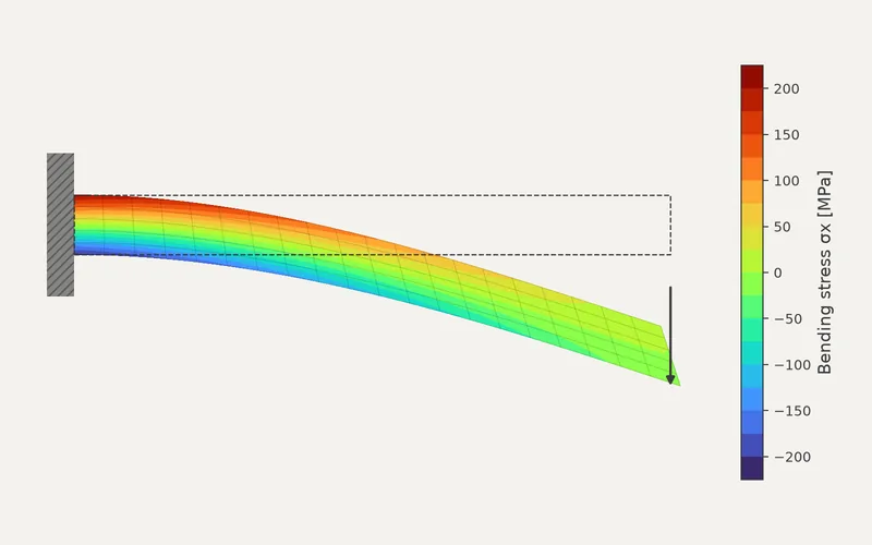
Cantilever bending
Bending stress and tip deflection checked against Euler–Bernoulli beam theory.
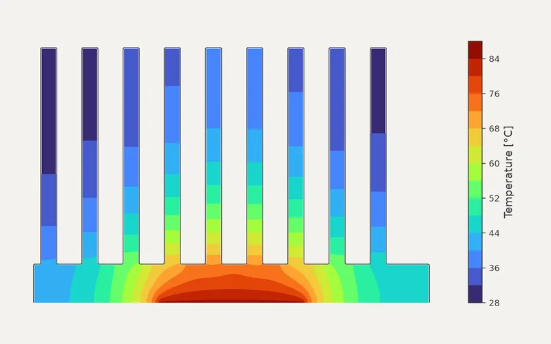
Heat sink conduction
Steady conduction with fin convection, showing where added fin height stops paying off.
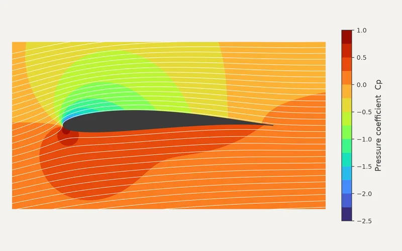
Airfoil pressure distribution
Compared with the Joukowski solution and the Kutta–Joukowski lift theorem.
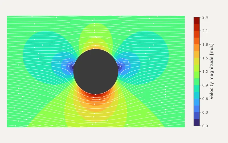
Rotating cylinder flow
Asymmetric velocity field and Magnus side force, in agreement with potential-flow theory.
Need a similar analysis?
Tell us about the part, the loads and the decision you need to make.